SMK MAMBAU

SMK MAMBAU

Sunday 1 April 2012

What is immersive multimedia?


These terms refer to computer-generated simulation of reality with physical, spatial and visual dimensions. This interactive technology is used by architects, science and engineering researchers, and the arts, entertainment and video games industry.
 
Virtual reality systems can simulate everything from a walk-through of a building prior to construction to simulations of aircraft flight and three dimensional computer games.
 
Immersive technologies and virtual reality are powerful and compelling computer applications by which humans can interface and interact with computer generated environments in a way that mimics real life sense engagement.
 
Although mostly known for its application in the entertainment industry the real promise lies in such fields as medicine, science, engineering, oil exploration, data visualization and the military to name just a few.
 
As 3D and immersive technology becomes more integrated and available for a wide range of applications. It l requires well-designed user interfaces and innovative content for the next generation of computer games and integrated technology like mobile devices, distributed web systems and desktop applications.

Core concepts.......

Core concepts

At their core, all models of ubiquitous computing share a vision of small, inexpensive, robust networked processing devices, distributed at all scales throughout everyday life and generally turned to distinctly common-place ends. For example, a domestic ubiquitous computing environment might interconnect lighting and environmental controls with personal biometric monitors woven into clothing so that illumination and heating conditions in a room might be modulated, continuously and imperceptibly. Another common scenario posits refrigerators "aware" of their suitably tagged contents, able to both plan a variety of menus from the food actually on hand, and warn users of stale or spoiled food.
Ubiquitous computing presents challenges across computer science: in systems design and engineering, in systems modelling, and in user interface design. Contemporary human-computer interaction models, whether command-line, menu-driven, or GUI-based, are inappropriate and inadequate to the ubiquitous case. This suggests that the "natural" interaction paradigm appropriate to a fully robust ubiquitous computing has yet to emerge - although there is also recognition in the field that in many ways we are already living in an ubicomp world. Contemporary devices that lend some support to this latter idea include mobile phones, digital audio players, radio-frequency identification tags, GPS, and interactive whiteboards.
Mark Weiser proposed three basic forms for ubiquitous system devices, see also Smart device: tabs, pads and boards.
  • Tabs: wearable centimetre sized devices
  • Pads: hand-held decimetre-sized devices
  • Boards: metre sized interactive display devices.
These three forms proposed by Weiser are characterized by being macro-sized, having a planar form and on incorporating visual output displays. If we relax each of these three characteristics we can expand this range into a much more diverse and potentially more useful range of Ubiquitous Computing devices. Hence, three additional forms for ubiquitous systems have been proposed:[5]
  • Dust: miniaturized devices can be without visual output displays, e.g., Micro Electro-Mechanical Systems (MEMS), ranging from nanometres through micrometers to millimetres. See also Smart dust.
  • Skin: fabrics based upon light emitting and conductive polymers, organic computer devices, can be formed into more flexible non-planar display surfaces and products such as clothes and curtains, see OLED display. MEMS device can also be painted onto various surfaces so that a variety of physical world structures can act as networked surfaces of MEMS.
  • Clay: ensembles of MEMS can be formed into arbitrary three dimensional shapes as artefacts resembling many different kinds of physical object (see also Tangible interface).
In his book The Rise of the Network Society, Manuel Castells suggests that there is an ongoing shift from already-decentralised, stand-alone microcomputers and mainframes towards entirely pervasive computing. In his model of a pervasive computing system, Castells uses the example of the Internet as the start of a pervasive computing system. The logical progression from that paradigm is a system where that networking logic becomes applicable in every realm of daily activity, in every location and every context. Castells envisages a system where billions of miniature, ubiquitous inter-communication devices will be spread worldwide, "like pigment in the wall paint".

History

Mark Weiser coined the phrase "ubiquitous computing" around 1988, during his tenure as Chief Technologist of the Xerox Palo Alto Research Center (PARC). Both alone and with PARC Director and Chief Scientist John Seely Brown, Weiser wrote some of the earliest papers on the subject, largely defining it and sketching out its major concerns.[6][7][8]
Recognizing that the extension of processing power into everyday scenarios would necessitate understandings of social, cultural and psychological phenomena beyond its proper ambit, Weiser was influenced by many fields outside computer science, including "philosophy, phenomenology, anthropology, psychology, post-Modernism, sociology of science and feminist criticism." He was explicit about "the humanistic origins of the ‘invisible ideal in post-modernist thought'",[8] referencing as well the ironically dystopian Philip K. Dick novel Ubik.
Dr. Ken Sakamura of University of Tokyo, Japan leads the Ubiquitous Networking Laboratory (UNL), Tokyo as well as the T-Engine Forum. The joint goal of Sakamura's Ubiquitous Networking specification and the T-Engine forum, is to enable any everyday device to broadcast and receive information.[9][10]
MIT has also contributed significant research in this field, notably Things That Think consortium (directed by Hiroshi Ishii, Joseph A. Paradiso and Rosalind Picard) at the Media Lab[11] and the CSAIL effort known as Project Oxygen.[12] Other major contributors include Georgia Tech's College of Computing, NYU's Interactive Telecommunications Program, UC Irvine's Department of Informatics, Microsoft Research, Intel Research and Equator,[13] Ajou University UCRi & CUS.[14]

Pervasive Computing ( Ubiquitous Computing )

Contents

 [hide


Pervasive computing (also called ubiquitous computing) is the growing trend towards embedding microprocessors in everyday objects so they can communicate information.  The words pervasive and ubiquitous mean "existing everywhere." Pervasive computing devices are completely connected and constantly available. 

Pervasive computing relies on the convergence of  wireless technologies, advanced electronics and the Internet. The goal of researchers working in pervasive computing is to create smart products that communicate unobtrusively. The products are connected to the Internet and the data they generate is easily available.  

Privacy advocates are concerned about the "big brother is watching you" aspects of pervasive computing, but from a practical standpoint, most researchers feel it will improve efficiency.  In a 1996 speech, Rick Belluzo, who was then executive VP and general manager of Hewlett-Packard, compared pervasive computing to electricity. He described it as being "the stage when we take computing for granted. We only notice its absence, rather than its presence."

An example of a practical application of pervasive computing is the replacement of old electric meters with smart meters. In the past, electric meters had to be manually read by a company representative. Smart meters report usage in real-time over the Internet.  They will also notify the power company when there is an outage, reset thermostats according to the  homeowner's directives, send messages to display units in the home and regulate the water heater.


Ubiquitous computing (ubicomp) is a post-desktop model of human-computer interaction in which information processing has been thoroughly integrated into everyday objects and activities. In the course of ordinary activities, someone "using" ubiquitous computing engages many computational devices and systems simultaneously, and may not necessarily even be aware that they are doing so. This model is usually considered an advancement from the desktop paradigm. More formally, ubiquitous computing is defined as "machines that fit the human environment instead of forcing humans to enter theirs."[1]
This paradigm is also described as pervasive computing, ambient intelligence,[2] or, more recently, everyware,[3] where each term emphasizes slightly different aspects. When primarily concerning the objects involved, it is also physical computing, the Internet of Things, haptic computing,[4] and things that think. Rather than propose a single definition for ubiquitous computing and for these related terms, a taxonomy of properties for ubiquitous computing has been proposed, from which different kinds or flavors of ubiquitous systems and applications can be described.[5]

Hybrid

Hybrid networks use a combination of any two or more topologies in such a way that the resulting network does not exhibit one of the standard topologies (e.g., bus, star, ring, etc.). For example, a tree network connected to a tree network is still a tree network topology. A hybrid topology is always produced when two different basic network topologies are connected. Two common examples for Hybrid network are: star ring network and star bus network
  • A Star ring network consists of two or more star topologies connected using a multistation access unit (MAU) as a centralized hub.
  • A Star Bus network consists of two or more star topologies connected using a bus trunk (the bus trunk serves as the network's backbone).
While grid and torus networks have found popularity in high-performance computing applications, some systems have used genetic algorithms to design custom networks that have the fewest possible hops in between different nodes. Some of the resulting layouts are nearly incomprehensible, although they function quite well.[citation needed]
A Snowflake topology is really a "Star of Stars" network, so it exhibits characteristics of a hybrid network topology but is not composed of two different basic network topologies being connected. Definition : Hybrid topology is a combination of Bus,Star and ring topology.

Daisy chain

Except for star-based networks, the easiest way to add more computers into a network is by daisy-chaining, or connecting each computer in series to the next. If a message is intended for a computer partway down the line, each system bounces it along in sequence until it reaches the destination. A daisy-chained network can take two basic forms: linear and ring.
  • A linear topology puts a two-way link between one computer and the next. However, this was expensive in the early days of computing, since each computer (except for the ones at each end) required two receivers and two transmitters.
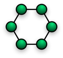
  • By connecting the computers at each end, a ring topology can be formed. An advantage of the ring is that the number of transmitters and receivers can be cut in half, since a message will eventually loop all of the way around. When a node sends a message, the message is processed by each computer in the ring. If a computer is not the destination node, it will pass the message to the next node, until the message arrives at its destination. If the message is not accepted by any node on the network, it will travel around the entire ring and return to the sender. This potentially results in a doubling of travel time for data.

Centralization

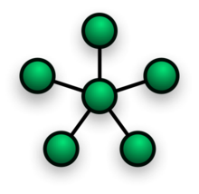
The star topology reduces the probability of a network failure by connecting all of the peripheral nodes (computers, etc.) to a central node. When the physical star topology is applied to a logical bus network such as Ethernet, this central node (traditionally a hub) rebroadcasts all transmissions received from any peripheral node to all peripheral nodes on the network, sometimes including the originating node. All peripheral nodes may thus communicate with all others by transmitting to, and receiving from, the central node only. The failure of a transmission line linking any peripheral node to the central node will result in the isolation of that peripheral node from all others, but the remaining peripheral nodes will be unaffected. However, the disadvantage is that the failure of the central node will cause the failure of all of the peripheral nodes also,

If the central node is passive, the originating node must be able to tolerate the reception of an echo of its own transmission, delayed by the two-way round trip transmission time (i.e. to and from the central node) plus any delay generated in the central node. An active star network has an active central node that usually has the means to prevent echo-related problems.

A tree topology (a.k.a. hierarchical topology) can be viewed as a collection of star networks arranged in a hierarchy. This tree has individual peripheral nodes (e.g. leaves) which are required to transmit to and receive from one other node only and are not required to act as repeaters or regenerators. Unlike the star network, the functionality of the central node may be distributed.
As in the conventional star network, individual nodes may thus still be isolated from the network by a single-point failure of a transmission path to the node. If a link connecting a leaf fails, that leaf is isolated; if a connection to a non-leaf node fails, an entire section of the network becomes isolated from the rest.

To alleviate the amount of network traffic that comes from broadcasting all signals to all nodes, more advanced central nodes were developed that are able to keep track of the identities of the nodes that are connected to the network. These network switches will "learn" the layout of the network by "listening" on each port during normal data transmission, examining the data packets and recording the address/identifier of each connected node and which port it is connected to in a lookup table held in memory. This lookup table then allows future transmissions to be forwarded to the intended destination only.

Decentralization

In a mesh topology (i.e., a partially connected mesh topology), there are at least two nodes with two or more paths between them to provide redundant paths to be used in case the link providing one of the paths fails. This decentralization is often used to advantage to compensate for the single-point-failure disadvantage that is present when using a single device as a central node (e.g., in star and tree networks). A special kind of mesh, limiting the number of hops between two nodes, is a hypercube. The number of arbitrary forks in mesh networks makes them more difficult to design and implement, but their decentralized nature makes them very useful. This is similar in some ways to a grid network, where a linear or ring topology is used to connect systems in multiple directions. A multi-dimensional ring has a toroidal topology, for instance.

A fully connected network, complete topology or full mesh topology is a network topology in which there is a direct link between all pairs of nodes. In a fully connected network with n nodes, there are n(n-1)/2 direct links. Networks designed with this topology are usually very expensive to set up, but provide a high degree of reliability due to the multiple paths for data that are provided by the large number of redundant links between nodes. This topology is mostly seen in military applications.
Bus
In local area networks where bus topology is used, each node is connected to a single cable. Each computer or server is connected to the single bus cable. A signal from the source travels in both directions to all machines connected on the bus cable until it finds the intended recipient. If the machine address does not match the intended address for the data, the machine ignores the data. Alternatively, if the data matches the machine address, the data is accepted. Since the bus topology consists of only one wire, it is rather inexpensive to implement when compared to other topologies. However, the low cost of implementing the technology is offset by the high cost of managing the network. Additionally, since only one cable is utilized, it can be the single point of failure. If the network cable is terminated on both ends and when without termination data transfer stop and when cable breaks, the entire network will be down.
Linear bus
The type of network topology in which all of the nodes of the network are connected to a common transmission medium which has exactly two endpoints (this is the 'bus', which is also commonly referred to as the backbone, or trunk) – all data that is transmitted between nodes in the network is transmitted over this common transmission medium and is able to be received by all nodes in the network simultaneously.[1]
Note: The two endpoints of the common transmission medium are normally terminated with a device called a terminator that exhibits the characteristic impedance of the transmission medium and which dissipates or absorbs the energy that remains in the signal to prevent the signal from being reflected or propagated back onto the transmission medium in the opposite direction, which would cause interference with and degradation of the signals on the transmission medium.
Distributed bus
The type of network topology in which all of the nodes of the network are connected to a common transmission medium which has more than two endpoints that are created by adding branches to the main section of the transmission medium – the physical distributed bus topology functions in exactly the same fashion as the physical linear bus topology (i.e., all nodes share a common transmission medium).
Notes:
  1. All of the endpoints of the common transmission medium are normally terminated using 50 ohm resistor.
  2. The linear bus topology is sometimes considered to be a special case of the distributed bus topology – i.e., a distributed bus with no branching segments.
  3. The physical distributed bus topology is sometimes incorrectly referred to as a physical tree topology – however, although the physical distributed bus topology resembles the physical tree topology, it differs from the physical tree topology in that there is no central node to which any other nodes are connected, since this hierarchical functionality is replaced by the common bus.

 Star

In local area networks with a star topology, each network host is connected to a central hub with a point-to-point connection. The network does not necessarily have to resemble a star to be classified as a star network, but all of the nodes on the network must be connected to one central device. All traffic that traverses the network passes through the central hub. The hub acts as a signal repeater. The star topology is considered the easiest topology to design and implement. An advantage of the star topology is the simplicity of adding additional nodes. The primary disadvantage of the star topology is that the hub represents a single point of failure.
Notes
  1. A point-to-point link (described above) is sometimes categorized as a special instance of the physical star topology – therefore, the simplest type of network that is based upon the physical star topology would consist of one node with a single point-to-point link to a second node, the choice of which node is the 'hub' and which node is the 'spoke' being arbitrary.[1]
  2. After the special case of the point-to-point link, as in note (1) above, the next simplest type of network that is based upon the physical star topology would consist of one central node – the 'hub' – with two separate point-to-point links to two peripheral nodes – the 'spokes'.
  3. Although most networks that are based upon the physical star topology are commonly implemented using a special device such as a hub or switch as the central node (i.e., the 'hub' of the star), it is also possible to implement a network that is based upon the physical star topology using a computer or even a simple common connection point as the 'hub' or central node.[citation needed]
  4. Star networks may also be described as either broadcast multi-access or nonbroadcast multi-access (NBMA), depending on whether the technology of the network either automatically propagates a signal at the hub to all spokes, or only addresses individual spokes with each communication.
Extended star
A type of network topology in which a network that is based upon the physical star topology has one or more repeaters between the central node (the 'hub' of the star) and the peripheral or 'spoke' nodes, the repeaters being used to extend the maximum transmission distance of the point-to-point links between the central node and the peripheral nodes beyond that which is supported by the transmitter power of the central node or beyond that which is supported by the standard upon which the physical layer of the physical star network is based.
If the repeaters in a network that is based upon the physical extended star topology are replaced with hubs or switches, then a hybrid network topology is created that is referred to as a physical hierarchical star topology, although some texts make no distinction between the two topologies.
Distributed Star
A type of network topology that is composed of individual networks that are based upon the physical star topology connected in a linear fashion – i.e., 'daisy-chained' – with no central or top level connection point (e.g., two or more 'stacked' hubs, along with their associated star connected nodes or 'spokes').

 Ring

A network topology that is set up in a circular fashion in which data travels around the ring in one direction and each device on the right acts as a repeater to keep the signal strong as it travels. Each device incorporates a receiver for the incoming signal and a transmitter to send the data on to the next device in the ring. The network is dependent on the ability of the signal to travel around the ring.[4]

 Mesh

Fully connected
The number of connections in a full mesh = n(n - 1) / 2.
Note: The physical fully connected mesh topology is generally too costly and complex for practical networks, although the topology is used when there are only a small number of nodes to be interconnected (see Combinatorial explosion).
Partially connected
Partially connected mesh topology
The type of network topology in which some of the nodes of the network are connected to more than one other node in the network with a point-to-point link – this makes it possible to take advantage of some of the redundancy that is provided by a physical fully connected mesh topology without the expense and complexity required for a connection between every node in the network.
Note: In most practical networks that are based upon the partially connected mesh topology, all of the data that is transmitted between nodes in the network takes the shortest path between nodes,[citation needed] except in the case of a failure or break in one of the links, in which case the data takes an alternative path to the destination. This requires that the nodes of the network possess some type of logical 'routing' algorithm to determine the correct path to use at any particular time.

 Tree

Tree network topology


The type of network topology in which a central 'root' node (the top level of the hierarchy) is connected to one or more other nodes that are one level lower in the hierarchy (i.e., the second level) with a point-to-point link between each of the second level nodes and the top level central 'root' node, while each of the second level nodes that are connected to the top level central 'root' node will also have one or more other nodes that are one level lower in the hierarchy (i.e., the third level) connected to it, also with a point-to-point link, the top level central 'root' node being the only node that has no other node above it in the hierarchy (The hierarchy of the tree is symmetrical.) Each node in the network having a specific fixed number, of nodes connected to it at the next lower level in the hierarchy, the number, being referred to as the 'branching factor' of the hierarchical tree.This tree has individual peripheral nodes.
  1. A network that is based upon the physical hierarchical topology must have at least three levels in the hierarchy of the tree, since a network with a central 'root' node and only one hierarchical level below it would exhibit the physical topology of a star.
  2. A network that is based upon the physical hierarchical topology and with a branching factor of 1 would be classified as a physical linear topology.
  3. The branching factor, f, is independent of the total number of nodes in the network and, therefore, if the nodes in the network require ports for connection to other nodes the total number of ports per node may be kept low even though the total number of nodes is large – this makes the effect of the cost of adding ports to each node totally dependent upon the branching factor and may therefore be kept as low as required without any effect upon the total number of nodes that are possible.
  4. The total number of point-to-point links in a network that is based upon the physical hierarchical topology will be one less than the total number of nodes in the network.
  5. If the nodes in a network that is based upon the physical hierarchical topology are required to perform any processing upon the data that is transmitted between nodes in the network, the nodes that are at higher levels in the hierarchy will be required to perform more processing operations on behalf of other nodes than the nodes that are lower in the hierarchy. Such a type of network topology is very useful and highly recommended.
definition : Tree topology is a combination of Bus and Star topology.

Point-to-point.....


The simplest topology is a permanent link between two endpoints. Switched point-to-point topologies are the basic model of conventional telephony. The value of a permanent point-to-point network is unimpeded communications between the two endpoints. The value of an on-demand point-to-point connection is proportional to the number of potential pairs of subscribers, and has been expressed as Metcalfe's Law.

Permanent (dedicated)
Easiest to understand, of the variations of point-to-point topology, is a point-to-point communications channel that appears, to the user, to be permanently associated with the two endpoints. A children's tin can telephone is one example of a physical dedicated channel.
Within many switched telecommunications systems, it is possible to establish a permanent circuit. One example might be a telephone in the lobby of a public building, which is programmed to ring only the number of a telephone dispatcher. "Nailing down" a switched connection saves the cost of running a physical circuit between the two points. The resources in such a connection can be released when no longer needed, for example, a television circuit from a parade route back to the studio.
Switched:
Using circuit-switching or packet-switching technologies, a point-to-point circuit can be set up dynamically, and dropped when no longer needed. This is the basic mode of conventional telephony.

Topology.....

There are two basic categories of network topologies:

 1 Physical topologies     2 Logical topologies
The shape of the cabling layout used to link devices is called the physical topology of the network. This refers to the layout of cabling, the locations of nodes, and the interconnections between the nodes and the cabling.

The physical topology of a network is determined by the capabilities of the network access devices and media, the level of control or fault tolerance desired, and the cost associated with cabling or telecommunications circuits.

The logical topology, in contrast, is the way that the signals act on the network media, or the way that the data passes through the network from one device to the next without regard to the physical interconnection of the devices. A network's logical topology is not necessarily the same as its physical topology. For example, the original twisted pair Ethernet using repeater hubs was a logical bus topology with a physical star topology layout. Token Ring is a logical ring topology, but is wired a physical star from the Media Access Unit.

The logical classification of network topologies generally follows the same classifications as those in the physical classifications of network topologies but describes the path that the data takes between nodes being used as opposed to the actual physical connections between nodes. The logical topologies are generally determined by network protocols as opposed to being determined by the physical layout of cables, wires, and network devices or by the flow of the electrical signals, although in many cases the paths that the electrical signals take between nodes may closely match the logical flow of data, hence the convention of using the terms logical topology and signal topology interchangeably.

Logical topologies are often closely associated with Media Access Control methods and protocols. Logical topologies are able to be dynamically reconfigured by special types of equipment such as routers and switches.

The study of network topology recognizes eight basic topologies:[5]
  • Point-to-point
  • Bus
  • Star
  • Ring or circular
  • Mesh
  • Tree
  • Hybrid
  • Daisy chain